Crankshaft Manufacturing Process
Introduction
The crankshaft is located in the engine of a vehicle and converts the force created by the engine's pistons moving up and down into a force that moves the wheels in a circular motion so the car can go forward. Located inside the car's engine, it is connected to all the pistons in the engine and to the flywheel. To understand this shaft, it is important to understand how the pistons and the flywheel work.
A car engine produces motion by creating explosions inside it. The pistons, which are attached to the crankshaft in an engine, are moved up by the explosions inside the cylinders. As the shaft turns, it pushes those pistons back down, so that the next explosion can push it up again and start the cycle over again. The pistons are connected to the crankshaft to ensure it moves with them and keeps their movements regulated.
As there are few methods of manufacturing a crankshaft, this report explains how BILLET CRANKSHAFTS are manufactured.
FORCES IMPOSED ON A CRANKSHAFT
The obvious source of forces applied to a crankshaft is the product of combustion chamber pressure acting on the top of the piston. High-performance, normally-aspirated Spark-ignition (SI) engines can have combustion pressures in the 100-bar neighbourhood (1450 psi), while contemporary high-performance Compression-Ignition (CI) engines can see combustion pressures in excess of 200 bar (2900 psi). A pressure of 100 bar acting on a 4.00 inch diameter piston will produce a force of 18,221 pounds. A pressure of 200 bar acting on a 4.00 inch diameter piston produces a force of 36,442 pounds. That level of force exerted onto a crankshaft rod journal produces substantial bending and torsional moments and the resulting tensile, compressive and shear stresses.
However, there is another major source of forces imposed on a crankshaft, namely PistonAcceleration. The combined weight of the piston, ring package, wristpin, retainers, the connecting rod small end and a small amount of oil are being continuously accelerated from rest to very high velocity and back to rest twice each crankshaft revolution. Since the force it takes to accelerate an object is proportional to the weight of the object times the acceleration (as long as the mass of the object is constant), many of the significant forces exerted on those reciprocating components, as well as on the connecting rod beam and big-end, crankshaft, crankshaft, bearings, and engine block are directly related to piston acceleration.
So due to these many forces acting on this single component it makes one of the main force bearing components in an engine, making its’ production process very important and the need to be precise and accurate.
CRANKSHAFT MATERIALS
Medium-carbon steel alloys are composed of predominantly the element iron, and contain a small percentage of carbon (0.25% to 0.45%, described as ‘25 to 45 points’ of carbon), along with combinations of several alloying elements, the mix of which has been carefully designed in order to produce specific qualities in the target alloy, including hardenability, nitridability, surface and core hardness, ultimate tensile strength, yield strength, endurance limit (fatigue strength), ductility, impact resistance, corrosion resistance, and temper-embrittlement resistance. The alloying elements typically used in these carbon steels are manganese, chromium, molybdenum, nickel, silicon, cobalt, vanadium, and sometimes aluminium and titanium. Each of those elements adds specific properties in a given material. The carbon content is the main determinant of the ultimate strength and hardness to which such an alloy can be heat treated.
Chemistry of crankshaft Alloys
Nominal Percentages of Alloying Elements
Material | AMS | C | Mn | Cr | Ni | Mo | Si | V |
4340 | 6414 | 0.40 | 0.75 | 0.82 | 1.85 | 0.25 | ||
EN-30B | 0.30 | 0.55 | 1.20 | 4.15 | 0.30 | 0.22 | ||
4330-M | 6427 | 0.30 | 0.85 | 0.90 | 1.80 | 0.45 | 0.30 | 0.07 |
32-CrMoV-13 | 6481 | 0.34 | 0.55 | 3.00 | <0.30 | 0.90 | 0.25 | 0.28 |
300-M | 6419 | 0.43 | 0.75 | 0.82 | 1.85 | 0.40 | 1.70 | 0.07 |
Key: C = Carbon Mn = Manganese Cr = Chromium Ni = Nickel
Mo = Molybdenum Si = Silicon V = Vanadium AMS = Aircraft Material spec number
CRANKSHAFT MANUFACTURING PROCESSES
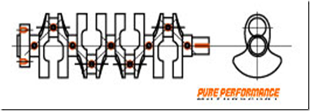
Crankshafts at the upper end of the motorsport spectrum are manufactured from billet. Billet crankshafts are fully machined from a round bar ("billet") of the selected material (Figure 1). This method of manufacture provides extreme flexibility of design and allows rapid alterations to a design in search of optimal performance characteristics. In addition to the fully-machined surfaces, the billet process makes it much easier to locate the counterweights and journal webs exactly where the designer wants them to be. This process involves demanding machining operations, especially with regard to counterweight shaping and undercutting, rifle-drilling main and rod journals, and drilling lubrication passages. The availability of multi-axis, high-speed, high precision CNC machining equipment has made the carved-from-billet method quite cost-effective, and, together with exacting 3D-CAD and FEA design methodologies, has enabled the manufacture of extremely precise crankshafts which often require very little in the way of subsequent massaging for balance purposes.
Manufacturing Process ofBillet Crankshafts Explained
Great care must be observed in the manufacture of the crankshaft since it is the most important part of the engine. While machining, the shaft must be properly supported between centres and special precautions should be taken to avoid springing. The journals and the crank pins are ground to exact size after turning. After this, the crankshaft is balanced. Large shafts of low speed engines are balanced statically. Crankshafts of high speed engines are balanced dynamically on special balancing machines. Most crankshafts are ground at the journals and crankpins. In some cases, grinding is followed by hand lapping with emery cloth.
Crankshaft used in high production automotive engines may be either billet, forged or cast.
Crankshaft used in high production automotive engines may be either billet, forged or cast.
High strength steels are carefully refined so as to remove as many of the undesirable impurities as possible (sulphur, phosphorous, calcium, etc.) and to more tightly constrain the tolerances, which define the allowable variations in the percentage of alloying elements. The highest quality steels are usually specified and ordered by reference to their AMS number (Aircraft Material Specification). These specs tightly constrain the chemistry, and the required purity can often only be achieved by melting in a vacuum, then re-melting in a vacuum to further refine the metal. Typical vacuum-processing methods are VIM and VAR.
What is VIM?
Vacuum Induction Melting (VIM) is a process for producing very high purity steels by melting the materials by induction heating inside a high-vacuum chamber.
What is VAR?
Vacuum Arc re-melting (VAR) is a refining process in which steels are re-melted inside a vacuum chamber to reduce the amount of dissolved gasses in the metal. Heating is by means of an electric arc between a consumable electrode and the ingot.
There are other ultra-high-strength steels that are not carbon steels. These steels, known as "maraging" steels, are refined so as to remove as much of the carbon as possible, and develop their extreme strength and fatigue properties as a by-product of the crystalline structures resulting from the large amounts of nickel (15% and up) and cobalt (6% and up) they contain. These steels can achieve extreme levels of strength and maintain excellent levels of impact resistance. Maraging alloys are not currently (2008) used for racing crankshafts but they have been used in certain extreme application connecting rods.
In the high performance crankshaft world, the nickel-chrome-moly alloy SAE-4340 (AMS-6414) has been a favourite in both forged and billet applications. It is used because of its very high strength and fatigue properties, coupled with good ductility and impact resistance at high strengths. SAE-4340 contains a nominal 40 points of carbon and is often described as "the standard to which other ultra-high strength alloys are compared".
Basic Steps of Manufacturing a Billet Crankshaft
- · Cutting to length and centering
- · Turning
- · Turnbroaching
- · Turn-turnbroaching
- · Internal milling
- · High speed external milling
- · Oil hole drilling
- · Roller burnishing
- · End machining
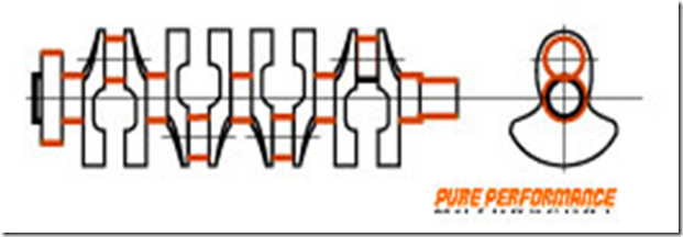
Manufacturing Process Explained Graphically
1) Shaping on the lathe – This process shaves the journals leaving a margin of finishing
2) Process to mill the pin - This process shaves the weight part coarsely, and shaves the pins leaving a margin of finishing.
3) The process to mill the weight - In order to make it the form of a crank shaft, the outside portion of weight and superfluous portion are shaved.
4) Conditioning quality and shot peening - Internal stress is removed, the structure is stabilized and hardness is set to HRC 28-32.
5) Shaping on the lathe for the 2nd time - This process shaved the journals leaving a margin of polishing.
6) Process to mill the pin - This process shaved the pins leaving a margin of polishing
7) The oil hole, the key slot, and the bolt hole processing - This process made the oil holes, the key slots, the pulley bolt holes, and the flywheel bolt holes.
8) The pin and the journal polishing process - This process polished the journals and the crank pins.
9) The dynamic balance adjustment process - In order to suppress oscillating of a crank as much as possible, the balance of a crank simple substance is measured and balance processing is performed.
10) The pin and the journal wrapping process - This process is to improve the degree of true circle and surface roughness in order to gain smooth rotation and reduction of friction.
11) The surface treatment process - Surface strength, durability of friction, and fatigue strength of the surface are improving. The surface becomes black by the surface treatment.
(There is effect which helps early fitting.)
(There is effect which helps early fitting.)
12) The final wrapping, bend correction, and inspection process - After the last wrapping, the bend which causes vibration is corrected. It is inspected after bend correction.
Quality Consideration
The difference between cast iron and nodular cast iron is the shape of the graphite particles in the iron. Cast iron is not just iron, pure iron is too soft to be used as a crankshaft. In regular cast iron, the graphite particles are flakes. In nodular cast iron, they are spherical nodules. This gives the cast iron more strength and flexibility.
To make billet crankshafts, a much larger bar of steel is forged into a cylinder shape as large as the total diameter of the finished crank, then it is machined to the final shape. As you can imagine that is a lot more machining and final cost reflects this.
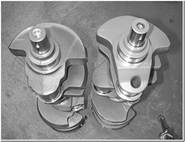
Cast crank on the left and Billet crank on the right
One thing to think about is that depending on the alloy used, a cast steel crank can be almost as strong as a forged crank.
There is a theory that while forging aligns the crystals of the steel, all the bending that is needed to make the final shape breaks some of those. Versus the billet, that while it doesn’t use as much pressure as forging and doesn’t produce as tight of a grain, it isn’t disrupted by bending. Instead it is machined to the final shape.
Tooling Required
To produce a crankshaft there are few main tools required:
1) Lathe machine – this machine is mainly used when manufacturing billet crankshafts as it requires heavy machining.
2) Shaper – to shape, oil lubrication paths
3) Precision Drills - to create hole to make sure oil goes through the crankshaft to keep it lubricated, so to cool.
4) Milling machine – a part of machining process to finalise/shape the crankshaft.
Possible Defects in Manufacturing
Conclusion
From all of the above we can conclude that for a better finish and accuracy billet crankshafts are the best, while forged crankshafts can be used for heavy duty purposes. Cast crankshafts are suitable for day today use.
Though billet crankshafts take time and money to be manufactured they are the most effective crankshafts out in the engineering field. Not to count out the accuracy, precision, ability to customize counter weights without mouldings and most importantly the whole crankshaft is one whole product.


